A modular machine guarding system is the right choice when you need a perimeter that can expand, reconfigure, or be reused as equipment changes, but only if you confirm access points, safety distances, gate types, opening sizes, and the exact machine mix before ordering so the system can scale without creating gaps, pinch points, or costly rework.
What a modular machine guarding system is, and when it makes sense
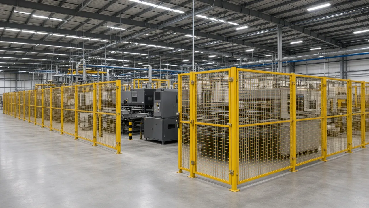
A modular machine guarding system uses standardized panels, posts, gates, and corners that bolt together to form a machine perimeter. Unlike custom fixed fencing fabricated and welded on site, modular guarding is designed to assemble quickly, come apart cleanly, and be reconfigured when a line changes.
That matters in plants where equipment does not stay still. If you plan to add a second robot, extend a conveyor, move a pallet station, or rebalance a packaging line, modular guarding gives you a layout that can change with the process instead of forcing the process to fit a fixed fence.
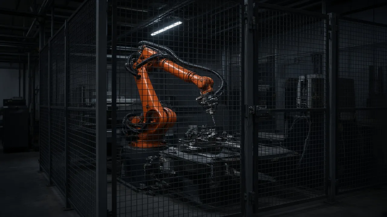
This approach fits many machine guarding applications, including robot cells, palletizing, welding, conveyors, CNC machine tools, packaging, and material handling. It is strongest when the process is likely to evolve, when installation speed matters, or when you want to standardize one guarding platform across multiple lines.
The trade-off is simple: flexibility only works if the first layout is planned carefully. If you draw the perimeter too tight, place a gate in the wrong place, or ignore future expansion space, the system becomes harder to adapt later.
How to decide whether modular guarding is the right buy
Before you specify a fence system, answer the layout question first: is this a fixed cell or a process that may grow?
- Is the equipment likely to move, expand, or add another machine later?
- Will operators need frequent access for loading, inspection, or jam clearing?
- Will forklifts, carts, pallets, or large tools enter the perimeter?
- Do you need visibility into the process, or do you need containment of chips, coolant, flash, or spatter?
- Is the line likely to be reconfigured for a different product in the next few years?
Choose a modular machine guarding system if the answer to most of those questions is yes. Choose a highly custom fixed fence only if the process is essentially permanent and the opening requirements are unlikely to change.
The layout decisions that determine whether the system scales cleanly
Set the perimeter around the process, not just the machine footprint
One of the most common planning errors is tracing the fence tightly around the machine base to save floor space. That may look efficient on a drawing, but it often leaves too little room for maintenance access, cable and hose service, gate travel, cleaning, or operator movement.
Think about the full working envelope, not just the footprint. Leave room for technicians to reach motors, sensors, panels, and lubrication points without having to remove guarding. If the process includes a robot, conveyor, or transfer device, include its sweep, load, and service zones before finalizing the perimeter.
Place gates for workflow, not convenience alone
Gate placement controls how people and material move through the cell. A good scalable layout usually has a primary operator access gate and, when needed, a second access point for maintenance, tooling, or material entry. For many installations, the type of gate matters just as much as the location.
Review the available safety gates and the integrated safety gate handle set options before you finalize the layout. A swing gate may be ideal where there is enough aisle space. A sliding or folding gate may be better where the aisle is tight or where a future line extension must remain clear.
If the gate opens into a busy aisle, make sure its travel does not conflict with carts, pallet traffic, or nearby equipment. If the gate is expected to be moved later, keep the surrounding fence geometry simple so the change does not trigger a full redesign.
Choose panel type by hazard, not by appearance
Different hazards call for different panel types. The best modular layout often mixes panel materials within the same perimeter, as long as the structural system remains compatible and the risk assessment supports the choice.
| Panel type | Best use | Main advantage | Main limitation |
|---|---|---|---|
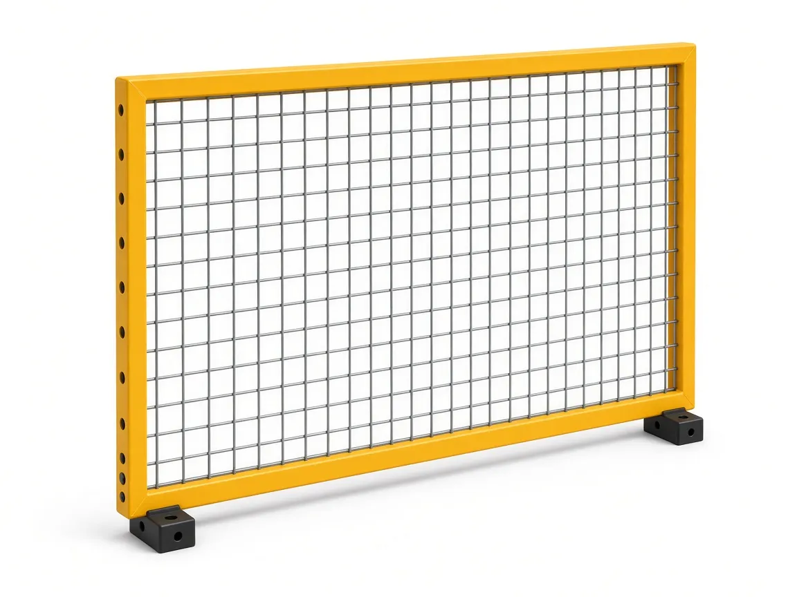
| Wire mesh | General perimeter separation, robot cells, conveyors | High visibility and airflow | Does not block chips, spatter, or fluids |
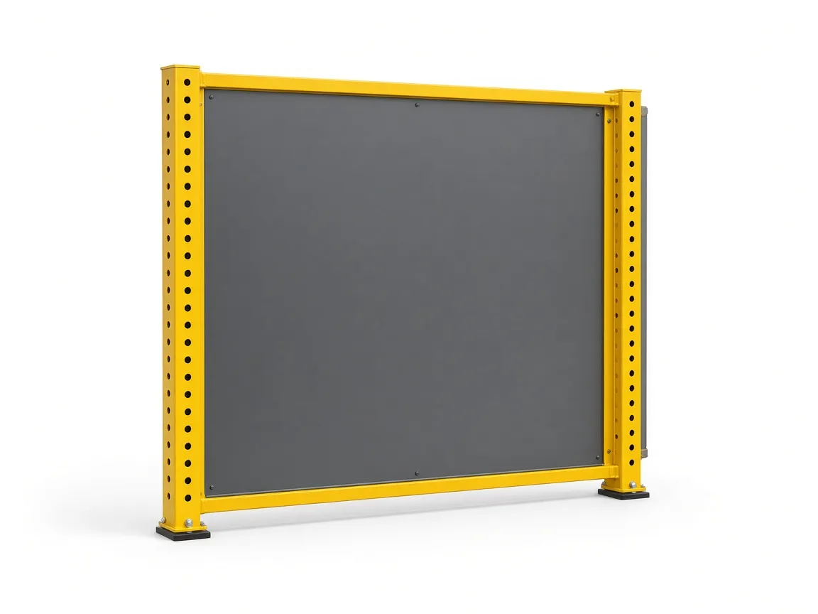
| Sheet metal | Welding cells and heavy debris zones | Helps block flash, spatter, and noise | Reduces visibility into the process |
| Polycarbonate | CNC machines and machine tending | Contains chips and coolant while preserving visibility | Can scratch if cleaned improperly |
For product details, compare wire mesh panels, sheet metal panels, and polycarbonate panels. If the process is welding, use sheet metal where spatter and flash are a concern. If the process is machining, polycarbonate may make more sense where visibility and chip containment matter. If the goal is simple separation and access control, wire mesh is often the most practical starting point.
Keep the expansion path open
If you expect future growth, reserve one or more sides of the perimeter for it. That means keeping electrical drops, fixed equipment, and permanent obstructions out of the path where the fence may extend later. A straight, simple edge is easier to extend than a perimeter with odd offsets and custom infill pieces.
Standardized bay widths also help. When the original layout follows a repeatable module, later expansion can usually be handled with matching panels and posts instead of one-off fabrication. That is where modular guarding creates real value: the second phase becomes an extension, not a redesign.
Standards and safety checks that affect the final layout
A modular fence is only one part of the safety strategy. The final layout should be based on a documented risk assessment by a competent person or team familiar with the machine, the process, and the current editions of the applicable standards.
At a minimum, the design should be checked against the standards that apply to the specific application. In general terms:
- OSHA 29 CFR 1910.212 addresses general machine guarding requirements.
- ANSI B11.0 and ANSI B11.19 address risk reduction and safeguarding performance for machinery.
- ANSI/A3 R15.06 addresses industrial robot systems and integration in the U.S. market.
- ISO 12100 addresses risk assessment and risk reduction.
- ISO 13849-1 addresses safety-related parts of control systems.
- ISO 13855 addresses the positioning of safeguards with respect to approach speeds.
- ISO 13857 addresses safety distances to prevent reaching hazard zones.
- ISO 14119 addresses interlocking devices associated with guards.
- ISO 14120 addresses general requirements for the design and construction of guards.
The key point is that the fence layout must support the safeguarding method, not replace it. If a gate is interlocked, the separation distance still has to be correct. If a light curtain is part of the system, its position must be coordinated with the stopping time and the approach distance. If you are unsure about a clause or a dimensional requirement, check the current edition of the standard before freezing the layout.
For more detail on how fence positioning relates to separation distances and guard height, see Machine Safety and our ISO 13857 safety distance guide. For a broader standards overview, the OSHA machine guarding requirements guide is also useful.
How to scale a modular guarding layout in phases
The best way to think about a modular layout is in phases. The first installation should solve today’s hazard. The geometry should also make it easy to extend, shift, or reconfigure later.
Phase 1 — Build the first cell for today’s process
Start by fencing the active hazard zone, not the broadest possible future vision. Map the operator access points, maintenance entry points, and material flow paths. Mark the side that is most likely to expand later so the project team knows where not to place permanent obstructions.
At this stage, document the intended future use of each wall. A clear note on the layout drawing can prevent a maintenance pipe, a cable tray, or a staging rack from being installed where the next enclosure extension will need to go.
Phase 2 — Add equipment without redesigning the whole perimeter
When a second machine or a conveyor extension is added, the goal is to open only the section that needs to change. Remove the end run or corner assembly, extend the line with matching modular posts and panels, and close the new opening with standard components. Because the parts are standardized, the expansion can usually be done without cutting or welding on site.
This is where modular guarding saves time and preserves consistency. The original layout remains recognizable, the safety logic stays intact, and the added equipment can be brought into the perimeter with less disruption than a fully custom rebuild.
Phase 3 — Reconfigure when the process changes
Some plants do not just expand; they change function. A welding cell may later become a multi-process assembly area. A machining cell may add a second spindle or a different fixture. In those cases, the perimeter may need different panels, a different gate style, or a new access location.
Examples of useful reconfiguration include:
- Replacing mesh with sheet metal in zones with flash, spatter, or debris
- Replacing a swing gate with a sliding or folding gate when aisle space tightens
- Adding a second access point for maintenance while keeping operator access controlled
- Extending the enclosure to cover a new robot, conveyor, or transfer station
Worked examples of scalable layouts
Example 1: Robot cell with a future conveyor addition
An integrator designs a robot cell around a single robot, fixture, and operator load station. The future conveyor is not installed yet, but the engineering team already knows where it will enter the cell. Instead of boxing in that side of the perimeter, they leave a straight run with a removable end section. When the conveyor arrives, the layout extends with minimal change to the original fence.
Why it works: the future expansion path was protected from day one, so the second phase fits the first phase rather than fighting it.
For application-specific planning, see robot cell guarding and conveyor guarding.
Example 2: CNC tending area that may gain another machine
A machine shop installs a guarded CNC tending station with chip and coolant containment. The initial perimeter uses polycarbonate near the machining zone so the operator can see the process while keeping debris contained. The far side of the enclosure is kept straight so a second machining center can be added later without a complete redesign.
Why it works: the layout separates the current machine from the future machine bay and uses the panel type that fits the hazard instead of forcing a one-size-fits-all fence.
For more on this application, review CNC machine guarding and polycarbonate machine panels.
Example 3: Palletizing cell that may expand to a second pallet position
A packaging line adds a robotic palletizer. The perimeter needs wide access for pallets and forklifts, so the main gate is selected with aisle flow in mind. The adjacent side is left simple and straight, with space reserved for a future pallet station or infeed change. When production expands, the new equipment ties into the existing fence without requiring a new enclosure.
Why it works: the team planned for material movement first, then designed the fence around that flow instead of trying to force traffic through a narrow opening.
For this type of project, see palletizing guarding and warehouse and material handling guarding.
Common mistakes that make modular systems hard to expand
Even a good modular product can be difficult to use if the layout is poorly planned. Avoid these common mistakes:
- Fencing too close: leaving no room for maintenance, cleaning, or process change.
- Blocking future paths: putting a gate, post, or electrical run where the next extension should go.
- Ignoring swing or slide envelopes: choosing a gate style without checking aisle congestion or nearby equipment.
- Mixing panel types without a hazard reason: using different materials because they are available, not because they fit the application.
- Skipping the distance check: assuming the fence is enough without verifying the safeguarding distances and control response.
- Failing to document phase two: ordering a closed rectangle with no clear expansion point.
If you are preparing a new line, a rework, or a plant expansion, a structured checklist can prevent most of these issues before they reach the floor. A planning worksheet is especially helpful when multiple departments are involved in the decision.
For a more detailed pre-installation process, see our machine guarding checklist for new equipment installations and the machine guarding fence layout checklist for U.S. plants.
What to confirm before you order
Before you request a quote, gather the basic information that will let the guarding layout be engineered correctly the first time. This is the shortest list that still gives the engineer enough detail to work with:
- Current machine footprint and likely future footprint
- Overall perimeter dimensions and available floor space
- Gate locations, swing directions, and required clear openings
- Operator access points and maintenance access points
- Material entry and exit paths, including pallets or carts
- Required panel height and any visibility or containment needs
- Floor mounting conditions and anchor constraints
- Which side of the enclosure is intended for future expansion
- Any drawing, CAD file, or basic dimension sketch you already have
If you already know the application, you can also start from a product or solution page and work backward into the layout. That is often the fastest route for buyers comparing options across robot cells, conveyors, welding lines, and machine tending. The key is to connect the application to the access pattern before the fence is specified.
How ZYD Technology supports the layout step
If you are still deciding whether modular guarding fits your project, send your machine layout, CAD file, or basic dimensions for an engineering review. ZYD Technology reviews access points and safety distances and returns a 2D or 3D guarding layout before you order. That makes it easier to compare options, identify expansion space, and avoid surprises during installation.
You can start with the engineering review page or request a quote if you are ready to share project details. ZYD Technology will reply within one business day.
Bottom line: when modular is the right buy
A modular machine guarding system is often the best choice when flexibility, future expansion, and layout reuse matter. It is not a shortcut around safety planning, and it will not fix a poorly defined process. But when the first layout is built with the second and third phases in mind, modular guarding can save time, reduce rework, and make future changes much easier.
If your line may grow or change, the right move is to plan the perimeter now with expansion in mind. Send the layout, and we can help you turn it into a guarding proposal that fits the machine, the workflow, and the next phase of the plant.