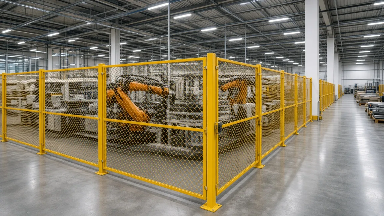
A new machine or production line needs a documented guarding review before purchase and again before startup. A practical machine guarding checklist helps engineers verify hazards, access points, safety distances, gate and interlock choices, maintenance access, and the common layout mistakes that lead to rework.
The goal is simple: make sure the guarding fits the installed machine, not just the concept drawing. That means reviewing the layout early, checking the machine’s operating modes, and confirming that the final installation still protects people when the line is running, being cleaned, or being serviced.
Why a machine guarding checklist matters on new equipment
There is a major difference between a machine that arrives with fencing and guarding that is actually correct for the installed plant layout. New installations often fail final review not because guards were omitted, but because access points, gate swing direction, pallet entry, cable routing, or routine maintenance tasks were not evaluated early in the design phase.
This checklist is for plant engineers, EHS managers, robot integrators, machine builders, and buyers who review drawings, RFQs, FATs, and SATs. It also helps when a project is still changing and the layout is not frozen. A documented risk assessment by a qualified person is still required. Applicable regulations and standards should be checked in their current editions, including OSHA 29 CFR 1910.212 and the other standards that apply to the machine and installation.
The checklist at a glance
Use this summary table before you dive into the details. It helps expose the items that usually get missed until the machine is already on the floor.
| Item to Verify | What Good Looks Like | Common Miss | Primary Owner |
|---|---|---|---|
| Hazard identification | All motion, pinch points, and process outputs are mapped | Only normal-cycle operation is reviewed | Integrator / EHS |
| Guarding concept | Perimeter, fixed, or hybrid guarding matches the task | Using fixed guards where frequent access is required | Design engineer |
| Safety distances | Distance is based on stopping time, approach speed, and geometry | Fence location is estimated instead of verified | Safety engineer |
| Openings and reach | Openings prevent reach-through, reach-over, and under-gap access | Mesh, gaps, or pass-throughs are oversized | Mechanical engineer |
| Gates and interlocks | Gate type and control behavior match the access need | Swing gates block aisles or lack proper interlock logic | Controls engineer |
| Material flow | Transfers are protected without creating a reach hazard | Open transfer windows are left unguarded | Layout engineer |
| Maintenance access | Service points are reachable without defeating safeguards | Routine service access is forgotten | Maintenance lead |
| Anchoring and floor conditions | Posts, bases, and anchors fit the actual slab | Floor joints, slope, or embedded items are ignored | Facilities / installer |
Step 1 — Define the machine hazards and operating modes
Map the hazards
Begin by documenting every mechanical and process hazard. Include pinch points, nip points, cutting, shearing, crushing, material ejection, robot motion, infeed and outfeed stations, and transfer mechanisms. Do not limit the review to automatic production. The guard must also support jog mode, teach mode, manual cleaning, jam clearing, tool changeovers, and maintenance. Many serious incidents happen during non-standard operation when the safest-looking layout does not match how the machine is actually used.
Identify who needs access and when
List every group that needs entry or reach-in access. Operators may need loading access. Maintenance teams need repair access. Setup technicians need calibration access. Robot programmers need teach access. Material handlers may need forklift or pallet access. Separate routine access from infrequent access, because access frequency often drives the choice between a fixed guard, an interlocked gate, or a different cell layout altogether.
If the application involves a robot, pallet flow, or automated transfer, start with the application-specific layout first. A general-purpose fence rarely solves a specific process problem without adjustment. The best place to start is usually the machine layout and application, not the fence catalog. For example, a robot cell, palletizing line, or conveyor transfer has different access needs and different openings than a CNC machine or welding station. See the related application pages for context: robot cell guarding, palletizing guarding, conveyor guarding, welding cell guarding, and CNC machine guarding.
Step 2 — Choose the right guarding concept
Decide between perimeter guarding, fixed guarding, or a hybrid
Determine whether the machine needs a full perimeter safety fence around a cell, local fixed guards bolted directly to the machine frame, or a hybrid layout that combines both approaches. Use perimeter guarding where a person must be excluded from a hazard zone. Use fixed guarding where access is not needed during normal operation. Use a hybrid when conveyors, transfer systems, and service points make one method alone impractical.
The trade-offs are straightforward. Mesh panels improve visibility and airflow. Sheet metal panels help contain sparks, spatter, chips, and debris. Polycarbonate panels keep the process visible while helping contain chips, coolant, and small parts. The guarding concept should follow the hazard, the process, and the maintenance routine, not just appearance or habit.
Match the panel type to the application
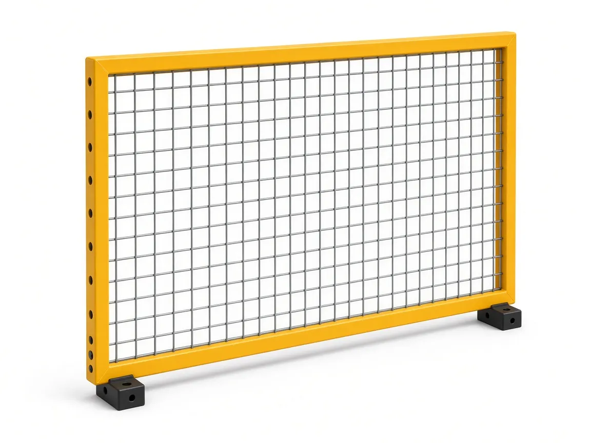
For general visibility and airflow, wire mesh safety fence panels are often the first option. Their 20 × 100 mm mesh pattern and modular format work well where operators need to see the process and airflow matters. For welding cells or dirty, high-debris processes, sheet metal guarding panels are better suited because they block flash, spatter, chips, and noise more effectively. Where visibility is critical and the process throws chips or coolant, polycarbonate machine guard panels are a strong choice.
Select the gate type based on use
Choose gate type based on access frequency, available floor space, and the size of what must pass through the opening. Single and double swing gates fit many pedestrian access points. Sliding, telescopic, or folding gates are often better where a swing arc would interfere with conveyors, forklifts, or adjacent machines. A gate should support the work pattern instead of forcing operators to work around it.
For a complete gate review, see the safety gates page. Where the gate needs integrated controls, escape release, or lockout capability, the safety gate handle set is worth reviewing during the layout stage.
Step 3 — Verify safety distances and openings
Review the relevant standards
Check the current editions of the standards that apply to the machine and installation. Common references include OSHA 29 CFR 1910.212 for general machine guarding, ANSI B11.0 for general safety requirements, ANSI B11.19 for safeguarding performance, ANSI/A3 R15.06 and ISO 10218-1/-2 for industrial robot safety, ISO 12100 for risk assessment principles, ISO 13849-1 for safety-related control systems, ISO 13855 for positioning safeguards relative to approach speed and stopping performance, ISO 13857 for safety distances that limit reach to hazard zones, ISO 14119 for interlocking devices, and ISO 14120 for the design and construction of fixed and movable guards. The applicable requirements depend on the machine, the controls, and the installation. Check the current edition before using any value or design assumption.
Check openings, reach-through, and reach-over
Verify that mesh openings, panel height, the gap below panels, and clearance around doors prevent personnel from reaching into hazard zones. A 7 ft 2 in (2,200 mm) guard height is a common standard panel height, but it is not a universal solution. The required height and opening size still need to be confirmed by risk assessment and the applicable safety-distance requirements.
Also check for reach-around and reach-over conditions. A fence that looks substantial can still be ineffective if the opening geometry allows a person to enter with an arm, tool, or body through the top, side, or bottom. Modular perimeters that can be installed without field cutting or welding help preserve engineered dimensions and reduce installation variability.
Confirm safety distance to the hazard
Guard placement is never arbitrary. The distance between the fence and the hazard must account for stopping time, approach speed, and the geometry of any opening or gate. If a person can reach the hazard before motion stops, the layout must be redesigned or the safeguarding arrangement must be revalidated. A guard that is physically strong but too close to the hazard still fails the safety objective.
When a project also uses detection devices such as light curtains, use the applicable safety-distance method for that device and stopping time. A supporting resource is the safety distance calculator, which explains how stopping distance calculations are typically approached for light curtains using recognized formulas.
Step 4 — Review every access point
Gates
Every access gate should have a clearly defined purpose: operator access, maintenance access, pallet access, or emergency access. Verify the swing direction, clear operating arc, latch side, and any interference with nearby equipment. Make sure the gate width matches the task. Oversized openings can create unnecessary reach hazards, while undersized openings can lead to field modifications that weaken the installation.
Interlocks and control integration
Verify that the interlock device is appropriate for the risk and the control architecture. Check restart prevention, guard locking where coasting hazards exist, and the logic used to grant permission for reset. Confirm what happens when the gate opens: the machine must transition to the required safe state, and the stopping performance must be validated. Avoid assuming that all interlocks behave the same way. The device, control system, and risk assessment all matter.
Escape release and lockout considerations
Where personnel can enter an enclosure and could become trapped, provide a means of escape release consistent with the risk assessment and applicable standards. Also define the lockout/tagout boundary early so maintenance does not depend on defeating the guard. Where a gate must support reset, permission, emergency stop, or escape functions in one assembly, an integrated handle solution can simplify the layout and the daily work process.
Step 5 — Check material flow, maintenance, and service tasks
Product flow openings
Automated manufacturing depends on material movement. Pallets, transfer conveyors, parts bins, part totes, and scrap removal points can all create openings in the guarding perimeter. The common miss is designing the opening to fit the product but not the person. A pass-through that is wide enough for a skid may also permit a reach-in hazard if the geometry is not controlled.
For applications where wide openings are needed, review the whole material flow path. This is especially important in palletizing guarding and warehouse and material handling guarding, where forklifts, pallet transfers, shuttles, or automated handling equipment may need controlled access through the perimeter.
Maintenance access
Machines need ongoing service: lubrication, filter replacement, sensor adjustment, vision calibration, tool change, and jam clearing. Verify that the guarded layout gives technicians a safe way to do those jobs without bypassing safeguards. If a temporary access method is required, define it in the procedure and make sure the controls support that process. Do not assume maintenance access will sort itself out after installation.
Utilities and housekeeping
Check cable trays, pneumatic hoses, coolant lines, and electrical conduits. These utilities should not force a guard to remain open or partially modified in the field. Housekeeping matters too. If operators or maintenance staff cannot clean the area without defeating the fence, the design is incomplete. A guarding layout should support normal plant housekeeping, not fight it.
Step 6 — Validate structure, installation, and floor conditions
Posts, anchoring, and alignment
Confirm that post spacing, base plates, and anchor hardware fit the actual slab conditions. Expansion joints, floor slope, embedded items, trench covers, and local floor damage can all affect installation quality. Modular guarding systems are helpful because they can be adjusted to the realities of a plant floor, but the final installation still has to be reviewed against the approved layout.
Seismic, vibration, and impact considerations
In busy plants, perimeter guarding may be exposed to forklift traffic, pallet impacts, and continuous vibration from nearby equipment. If the fence line runs near an aisle, a transfer point, or a warehouse lane, confirm that the posts, panels, and anchors can handle incidental contact without shifting the guarding envelope or loosening the installation over time.
Step 7 — Confirm documentation before purchase and startup
RFQ and submittal checklist
Before issuing a purchase order, verify that the package includes the items below:
- Machine layout drawings with critical dimensions
- Marked access points, maintenance zones, and transfer openings
- Panel type, panel height, and any special containment needs
- Gate type, swing direction, and clear opening width
- Interlock location and control interface details
- Safety distance assumptions and stopping time notes
- Floor anchoring and facility utility constraints
- Assigned responsibilities for installation, wiring, validation, and sign-off
FAT and SAT punch list
During FAT and SAT, verify that the physical installation matches the approved drawing set, every gate operates correctly, interlocks function as intended, no unplanned gaps or climb points exist, and the access procedure is documented. This is the time to catch issues that are cheap to fix and expensive to ignore.
Recordkeeping
Keep the final drawings, revision history, risk assessment notes, validation results, and training records together. Treat the guarding package as a controlled engineering document. A safe install is not just hardware; it is a maintained record of what was designed, why it was designed that way, and how it was validated.
Common miss points that cause rework
- Guarding is specified before the machine layout is frozen
- Gate swing conflicts with conveyors, pallets, or adjacent equipment
- Mesh or panel choice does not match the hazard
- Fence height or opening size is assumed instead of checked
- Safety distance is estimated rather than verified
- Maintenance access is forgotten until startup
- Floor joints, slope, or trench covers are discovered too late
- Interlock placement makes servicing awkward
- No one owns final validation and sign-off
Worked example: a robot palletizing cell
Consider a robotic palletizing cell with one operator loading side, one pallet transfer opening, and one maintenance entry gate. The operator side needs clear visibility and controlled access. The pallet transfer opening needs to accept the load without creating a reach-in hazard. The maintenance gate needs an interlock, appropriate reset logic, and enough clearance for service tasks. If the original fence line was drawn too close to the robot path, the opening may meet the material handling need but fail the safety-distance requirement. If the gate swings into a pallet lane, the door may be mechanically correct but operationally unusable. This is where the checklist pays for itself: it catches the conflict before fabrication or startup.
For this type of application, the guarding concept often needs to be tied to the process layout from the beginning. A cell that handles pallets is not the same as a small machine enclosure, and a robot system is not the same as a static workcell. The layout should drive the guarding, not the other way around.
One-page printable checklist
Use this short version in design reviews or startup meetings:
- Hazards identified for every operating mode
- Users and access needs defined
- Guarding concept selected
- Panel type matches the process hazard
- Gate type and swing direction reviewed
- Safety distances checked against the approved layout
- Openings, gaps, and climb points reviewed
- Interlocks and reset logic confirmed
- Maintenance and lockout access defined
- Floor conditions and anchoring reviewed
- Documentation, validation, and training completed
Conclusion
A strong machine guarding checklist does more than define the guard. It helps you catch layout errors, access conflicts, unsafe openings, and control issues before the machine is bought, built, or started. If your project is still in the planning stage, review the layout now instead of after fabrication. Send your machine layout, CAD file, or basic dimensions to engineering, or request a quote through the quote form. ZYD Technology reviews access points and safety distances and can return a 2D/3D guarding layout before you order.