Plan a machine guarding fence layout by mapping hazards, access points, openings, and aisles before you choose panels or gates. Measure the machine footprint, service routes, and required entry points, then verify safety distances and workflow clearances so you avoid rework and noncompliant openings.
A practical layout process starts with the equipment, not the fence. The goal is to separate people from hazards without blocking production, maintenance, or material flow. Use this checklist to build a perimeter that fits the job the first time.
What a good machine guarding fence layout has to accomplish
An effective perimeter does more than mark off a hazard area. It should support daily work, maintenance access, and safe material movement while helping your team meet the applicable requirements in OSHA 29 CFR 1910.212, ANSI B11.0, ANSI B11.19, ANSI/A3 R15.06, ISO 12100, ISO 13855, ISO 13857, ISO 14119, ISO 14120, and NFPA 79 as applicable. Check the current edition of each standard for your application, and complete a documented risk assessment by a qualified person.
- Keep hazardous motion separated from operators and visitors.
- Preserve normal production flow and material transfer.
- Provide safe access for setup, cleaning, clearing jams, and maintenance.
- Support the right gate, interlock, and control strategy at each opening.
- Fit the available floor space without unnecessary field cutting or welding.
Unlike a generic overview, this guide gives you the measurements and decisions to make before you order a fence.
Start with the process, not the fence
List the equipment and tasks inside the perimeter
Begin by mapping everything inside the proposed perimeter. Include robots, CNC machine tools, conveyors, palletizers, fixtures, utility drops, sensors, and control cabinets. Then list every task that requires human interaction:
- Loading and unloading parts.
- Tool changes and setup.
- Jam clearing and fault recovery.
- Cleaning chips, coolant, debris, or spatter.
- Preventative maintenance and calibration.
Mark all approach paths and material flows
Trace how people and material actually move around the cell. Mark fork truck lanes, cart paths, operator walkways, and service routes for electricians or maintenance staff. If the fence blocks the real route, the layout will fail in the field, even if the panels themselves are correct.
If a gate or opening does not match the job it serves, operators will find a workaround. The layout has to fit the process, not just the boundary.
Measure the footprint accurately
What to capture from the floor plan or site walk
Take measurements from the floor plan, CAD file, or site walk before you size any fence sections. Record the machine footprint, the maximum dynamic working envelope, and the clearance to walls, columns, cable trays, pipe runs, and adjacent equipment. Note the exact locations of emergency stops, disconnects, HMI stations, vision hardware, and any floor-mounted utilities that could interfere with posts or gate swings.
Minimum dimensions to record before design
- Total cell length and width.
- Clearance to nearby equipment and structures.
- Available space for gate swing or sliding travel.
- Aisle widths outside the perimeter.
- Opening widths needed for parts, carts, pallets, or service tools.
- Any overhead or vertical obstructions.
If you already have a layout file or even rough dimensions, you can send your machine layout, CAD file or basic dimensions for a guarding layout review before you buy.
Decide where people must enter, and why
Access types to identify
Every opening should serve a specific purpose. Separate access by function so you can choose the right gate or safeguarding method for each one.
- Routine operator access for loading, unloading, and checks.
- Maintenance access for repairs and component replacement.
- Material access for pallets, fixtures, carts, or transfer devices.
- Emergency egress for quick exit from the area.
- Cleaning and inspection access.
Match each access point to the right gate or opening
Use the simplest gate style that fits the job and the available space. Single swing gates work well for normal pedestrian access. Double swing gates suit wider maintenance entry. Sliding gates help when swing clearance is limited. Folding or telescoping gates can solve tight layouts where a swing door would hit nearby equipment. When opening the perimeter exposes a hazard, use an interlocked gate and verify the required stop performance in the risk assessment.
Review available configurations on the Safety gates page with single swing, double swing, sliding, telescoping, and folding options.
Plan openings so they are large enough for the job, but not larger than needed
Opening checklist
For each opening, ask the following:
- Does it need to pass a person only, or also a cart, pallet, fixture, or tool?
- Will it be used during production or only during maintenance?
- Can the task be changed to avoid a larger opening?
- Does it need a gate, removable section, or protected transfer point?
Common opening mistakes
- Making every gate the same size.
- Oversizing openings just in case.
- Forgetting tool and cart clearance.
- Placing openings at corners where visibility is poor.
- Ignoring how larger openings affect reach distance and safeguarding.
A larger opening is not automatically safer or better. It can force longer reach distances, make guarding verification harder, and consume valuable floor space.
Build aisle and workflow space into the layout
Aisle planning checklist
Keep the perimeter from becoming an obstacle to the rest of the plant. Check the layout against these points:
- Keep routine walking paths outside the fence.
- Maintain clear travel lanes for forklifts and carts.
- Avoid pinch points between gate swings and nearby columns or equipment.
- Leave enough staging space so operators do not have to reach through the fence.
- Place service panels and controls where they can be accessed from outside the perimeter when possible.
Practical examples
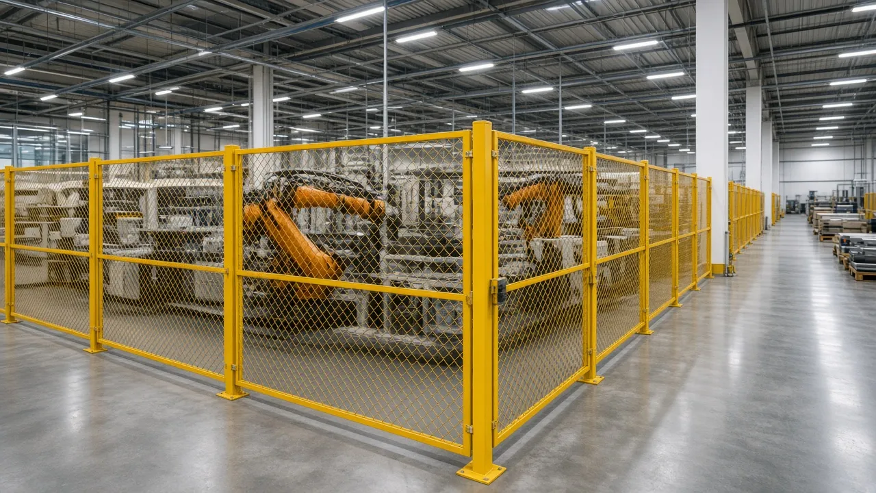
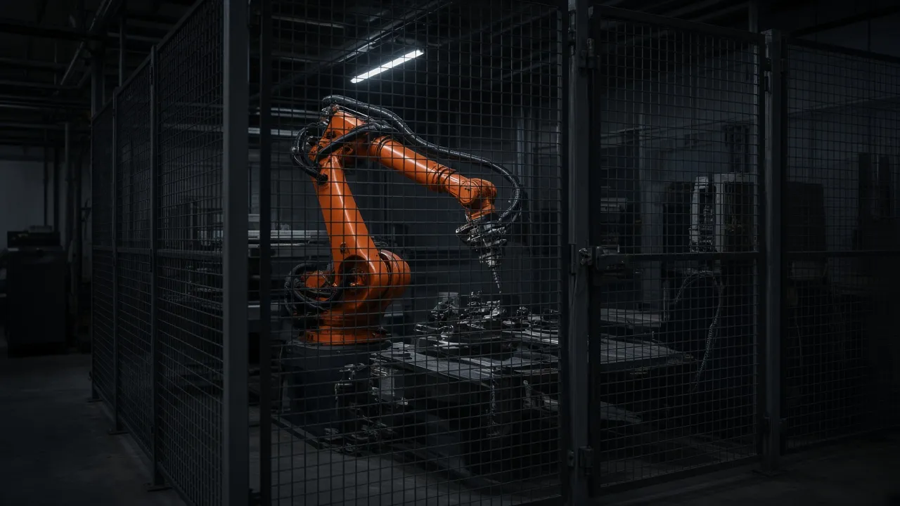
Robot cell: Put pedestrian access on the operator side, material transfer on the infeed or outfeed side, and maintenance access near the controller. This helps separate routine work from deeper service access.
CNC cell: Use clear panels where visibility matters and containment is needed. Place the operator gate where loading is natural and keep maintenance access away from the main traffic lane.
Conveyor line: Run long fence sections parallel to the conveyor and add only the access points needed at transfer stations and maintenance locations.
You can also review application-specific layouts on the Solutions page for robot cells, palletizing, welding, conveyors, packaging, CNC machine tools, and material handling.
Choose the panel and gate combination that fits the layout
Match the guarding style to the application
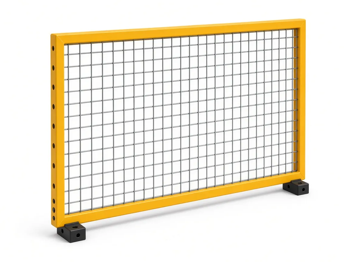
Select panel type based on the hazard and the process. Wire mesh is a strong general-purpose option where visibility and airflow matter. Sheet metal is often a better fit for welding cells, spatter, chips, or noise control. Polycarbonate helps contain chips, coolant, and small parts while keeping the process visible. The best choice is the one that solves the actual application problem, not just the perimeter problem.
See the available options on the Modular machine guarding products page for mesh, sheet metal, polycarbonate panels, and gate systems.
Consider standard panel widths and heights early
Plan around the available module sizes before you finalize the layout. Genmacs modular panels are available in widths from 100 to 1,500 mm (3.9 to 59.1 in) and heights from 1,000 to 2,250 mm (39.4 to 88.6 in), with 2,200 mm (86.6 in) as the standard height. A perimeter can close without cutting or welding on site when the layout is matched to those sizes. That reduces field work and helps the installation go together cleanly.
If your application calls for mesh, you can review the wire mesh safety fence panels with 20 × 100 mm mesh and EN ISO 14120 impact-tested construction. For welding or spatter control, see the sheet metal guarding panels for welding cells and chip containment. For visibility and containment, review the polycarbonate machine guard panels for chips, coolant, and small parts.
Account for safety distances and opening protection
What the layout must support
The fence has to be positioned so people cannot reach the hazard through or around the opening before hazardous motion has stopped. The correct distance depends on the hazard, the access method, the stopping performance, and the safeguard type. Do not set distances by fence height alone. Use the applicable standard and a documented risk assessment to verify the layout.
When to use a calculator or engineering review
For presence-sensing devices and related safeguarding methods, use a calculation method that matches the application and current edition of the standard. Our Safety Distance Calculator for light curtains shows the ISO 13855 and ANSI B11.19 formulas for reference, but it does not replace a full risk assessment or machine-specific validation.
For robotic systems, also verify the layout against robot cell guarding guidance for perimeter fencing, interlocked gates, and protected openings.
Checklist before you approve the layout
| Item | What to confirm | Why it matters | Done? |
|---|---|---|---|
| Hazard zone mapped | Full dynamic envelope of the machine or robot is known. | Prevents the fence from being placed too close to moving hazards. | [ ] |
| Operator access identified | All routine entry points are marked. | Supports normal workflow without unsafe shortcuts. | [ ] |
| Maintenance access identified | Service gates are sized for tools and repairs. | Reduces field modifications and downtime. | [ ] |
| Material flow confirmed | Forklift, cart, and pallet routes are clear. | Keeps guarding out of the way of production traffic. | [ ] |
| Gate type selected | Swing, sliding, folding, or telescoping gate matches the space. | Prevents swing conflicts and access problems. | [ ] |
| Opening width confirmed | Every opening is sized for the actual job. | Avoids oversizing and unnecessary exposure. | [ ] |
| Safety distance reviewed | Fence-to-hazard distance is checked against the stop time and safeguarding method. | Supports compliance with the applicable standard. | [ ] |
| Gate swing and aisle clearance checked | Doors do not hit equipment or block traffic. | Prevents installation issues and workflow conflicts. | [ ] |
| Obstructions cleared | Columns, pipes, conduits, and floor-mounted items are accounted for. | Reduces site surprises during installation. | [ ] |
| Egress paths remain clear | Plant walkways and exits are not blocked. | Supports plant safety and life-safety requirements. | [ ] |
| Module sizes confirmed | Panel widths and heights fit the floor plan without field cutting. | Speeds installation and improves fit. | [ ] |
| Risk assessment complete | A documented assessment has been completed by a qualified person. | Validates the final guarding approach. | [ ] |
Common machine guarding fence layout mistakes to avoid
- Designing the fence before the process: Start with machine motion, access, and workflow first.
- Forgetting maintenance access: A cell that is hard to service becomes a cell that gets bypassed.
- Blocking emergency routes: Keep required exits and walkways clear.
- Ignoring gate swing clearance: A door that hits a column or conveyor will create a field change.
- Oversizing openings: Big openings can create unnecessary reach exposure and complicate the safety design.
- Missing floor obstacles: Survey the site for conduits, pipes, cabinets, and anchor points before finalizing post locations.
- Skipping safety distance verification: Fence height alone does not determine reach protection.
Worked example: a simple layout for a robot or CNC cell
Consider a 15 ft by 20 ft (4,570 mm by 6,100 mm) robotic tending cell. The cell has a robot, a machine tool, a part conveyor, and a maintenance cabinet. A practical layout might look like this:
- Infeed side: A protected material transfer opening is sized only for the part-handling method, not for general pedestrian access.
- Operator side: A single interlocked pedestrian gate is placed where loading and inspection happen naturally.
- Maintenance side: A wider interlocked gate is located near the controller and service access points.
- Outside the fence: A 3 ft (914 mm) aisle is preserved for clear movement and service access.
- Panel selection: Mesh is used for visibility, or polycarbonate is used where chip and coolant containment are important.
When the layout is matched to the available module sizes, the perimeter can be assembled without field cutting or welding, which saves time and reduces rework.
What to send for a layout review before you buy
Before you place an order, send the information that helps an engineer validate the layout quickly and accurately:
- Floor plan, CAD file, or a sketch with basic dimensions.
- Machine footprint and hazardous motion envelope.
- Required operator, maintenance, and material access points.
- Locations of utilities, columns, and nearby equipment.
- Preferred panel style if you already have one in mind.
If you need a quote, use the request a quote form. ZYD Technology will review your layout, access points, and safety distances, then return a 2D/3D guarding layout before you order. That is the fastest way to turn a rough concept into a buildable machine guarding fence layout.