Perimeter guarding is the design process that controls access to industrial machinery while fitting the equipment footprint and supporting safe workflow. A good layout starts with a documented risk review, maps every hazard and access point, then places panels, gates, and openings where they protect people without blocking operation or maintenance.
For engineers, the fence is only one part of the system. The real work is deciding where the guard line belongs, which entries need interlocks, how material moves through the cell, and how to keep the layout buildable with standard modules. This guide walks through that sequence with practical examples for small and large footprints.
What perimeter guarding must do
The purpose of perimeter guarding is to prevent unintended access to hazardous machine motion while still allowing the access that the process actually needs. In practice, that means the perimeter must help control entry, prevent reach-in, support maintenance, and fit the plant’s traffic patterns. It is part of a safeguarding system, not a stand-alone fix.
Relevant standards and regulations may include OSHA 29 CFR 1910.212, ANSI B11.0, ANSI B11.19, ANSI/A3 R15.06, ISO 12100, ISO 13849-1, ISO 13855, ISO 13857, ISO 14119, ISO 14120, and NFPA 79, depending on the application and safeguarding method. Their current editions should be checked before final design, and a qualified person should document the risk assessment.
Machine Safety explains how safety fencing is selected and positioned, including guard heights, mesh openings, and impact testing considerations.
Start with the application, not the fence
Identify the hazard zones
Before you sketch a fence line, map the full hazard zone. Common hazards include robot motion, pinch points, conveyor nip points, stored energy in pneumatics or springs, material ejection, hot surfaces, welding flash, and chip or coolant spray. Also mark any zone that becomes hazardous only during setup, clearing jams, tool changes, or maintenance.
Map all access requirements
Every cell needs a realistic access plan. Separate routine operator access from infrequent maintenance access, and list every point where a person may need to enter or reach into the guarded area.
- Normal operator loading and unloading
- Jams, resets, and part retrieval
- Maintenance and cleaning
- Material flow, pallet movement, or forklift access
- Emergency egress from inside the perimeter
If you already have dimensions or a CAD file, Engineering can review access points and safety distances and return a 2D/3D guarding layout before you order.
| Design input | Why it matters | Typical source |
|---|---|---|
| Maximum motion envelope | Sets the minimum distance between the hazard and the guard line | Robot data, machine CAD, or field measurement |
| Routine access frequency | Helps determine the gate type, interlock need, and reset method | Operations and maintenance team |
| Material transfer points | Shows where protected openings or wide access gates are needed | Process flow and material handling plan |
| Floor obstacles and clearances | Prevents layout conflicts with columns, conduits, and anchors | Site survey |
Translate the footprint into a guarding plan
Measure the occupied envelope
Do not size the perimeter from the machine base alone. Measure the occupied envelope, which includes the static footprint, the maximum dynamic reach, doors, fixtures, cable tracks, and any required service clearance. The guard line usually sits outside that envelope so the cell remains safe and serviceable.
For a simple machine, that may be a straight rectangular run. For a large system, it may be an irregular loop that follows conveyors, worktables, and transfer points. In both cases, the goal is the same: the perimeter must keep people out of the hazard zone while still allowing the process to function.
Decide where the perimeter must be continuous
A good guarding layout forms a closed perimeter around the hazard zone. Any opening should be deliberate and protected. If the process requires a pass-through for pallets, conveyors, or parts, treat that opening as a design feature, not a gap to be filled later.
Use standard panel widths and post spacing to keep the layout modular. That helps the perimeter close without cutting or welding on site, and it makes future changes easier.
Pick the right panel type for the environment
Panel material should match the hazard and the process environment, not just the available footprint.
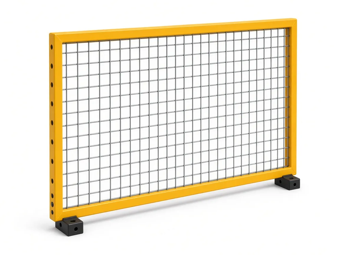
- Wire Mesh Panels (D Series) are a strong choice when visibility and general-purpose guarding matter.
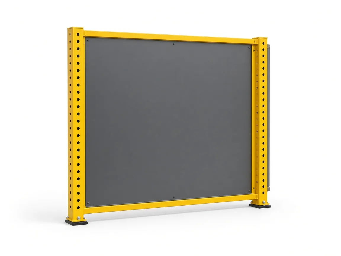
- Sheet Metal Panels (SM Series) fit welding cells, spatter-heavy areas, and applications where visibility is less important than containment or shielding.
- Polycarbonate Panels (PC Series) help when you need clear viewing while containing chips, coolant, or small parts.
If you are comparing materials for a specific application, the article Wire Mesh vs Polycarbonate vs Sheet Metal Machine Guards can help you narrow the choice.
Design the access points
Gate type selection
Gate selection should follow aisle space, access frequency, and the way people and materials move around the cell. Single swing gates work well when there is room for the door leaf. Double swing gates are useful for wider openings. Sliding, folding, and telescopic gates help when clearance is tight or a swinging leaf would block traffic.
Every gate that allows access to a hazardous area should be interlocked as part of the safeguarding system. The gate should fit the operation, not force the operation to adapt to the gate.
Safety Gates covers single and double swing, sliding, telescopic, folding, and ergonomic gate options with interlocks.
Gate hardware and handles
A gate needs hardware that supports the required safety functions. An integrated handle set can combine door operation, escape release, lockout-tagout capability, reset, permission request, and emergency stop controls in one place. That improves usability and helps keep the gate function consistent.
Safety Gate Handle Set describes the integrated handle options for interlocked gates.
Two worked examples
Example 1: Small machine footprint
Scenario: A compact CNC machining center with a 6 ft × 6 ft (1,800 mm × 1,800 mm) footprint. Operators load from the front, and maintenance access is needed at the rear for the coolant system and tool changer.
Layout approach: The guard line is placed outside the full operating envelope, not just the base frame. A rectangular perimeter is set around the machine with enough clearance for maintenance access and gate hardware. The front side gets a single swing interlocked gate for the operator, while the rear and sides use fixed mesh panels. Because the layout is built from standard panel widths, the perimeter closes without field cutting or welding.
Why this works: The small footprint is simple, but it still needs access planning. The operator gate stays on the preferred work side, the service side remains protected, and the layout leaves room for panel installation and future maintenance.
Example 2: Large irregular footprint
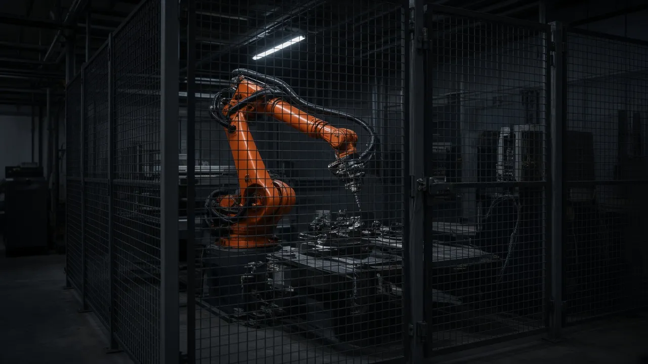
Scenario: A robotic palletizing cell with infeed and outfeed conveyors, a central robot, and a stretch wrapper. The overall space is 25 ft × 15 ft (7,600 mm × 4,600 mm), and forklifts occasionally service the area.
Layout approach: The perimeter follows the process, not a perfect rectangle. Long runs protect the robot sweep zone, while transfer points are handled as controlled openings. A wide double swing gate is placed on the side with the best maintenance and material staging access. Conveyor interfaces are protected with a combination of physical barrier and appropriate safeguarding where people must approach the opening.
Why this works: Large footprints usually fail when the fence ignores traffic patterns. Here, the gate location supports maintenance and forklift access, the conveyor interfaces stay controlled, and the modular layout adapts to the irregular shape without custom fabrication.
For similar applications, see Robot Cell Guarding, Palletizing Guarding, Conveyor Guarding, and Warehouse & Material Handling Guarding.
| Footprint type | Main access challenge | Typical guarding approach |
|---|---|---|
| Small CNC or compact cell | Limited aisle space and frequent operator access | Rectangular mesh perimeter with one interlocked operator gate |
| Large palletizing or conveyor line | Long perimeter runs, transfer openings, and forklift traffic | Mixed-panel perimeter with wide interlocked gates and controlled openings |
A practical sequence for finalizing the layout
Use this sequence to move from concept to order:
- Collect inputs: Gather CAD files, floor plans, machine dimensions, photos, and utility locations.
- Mark hazards and access points: Identify every place where a person could enter, reach, or service the equipment.
- Set the guard line: Place the perimeter outside the motion envelope while preserving the required clearances.
- Assign panels and gates: Choose mesh, sheet metal, or polycarbonate panels and select the gate type that fits the workflow.
- Check openings and interfaces: Review conveyors, pallet pass-throughs, floor anchors, columns, and conduit routes.
- Verify the safety basis: Confirm the layout against the applicable standards and complete the risk assessment with a qualified person.
Before you release the job, use this short checklist:
- Does the perimeter fully enclose the hazard zone?
- Are all access gates located where people actually need them?
- Do the gates open, slide, or fold without blocking aisles?
- Are interlocks specified for every gate that provides entry?
- Are transfer openings protected in a way that matches the risk?
- Can the layout be installed without on-site cutting or welding?
Common mistakes that create bad perimeter guarding
- Fence too close to the machine: Leaves no room for maintenance, cable routing, or safe access.
- Too few access points: Forces people to walk around the cell or bypass the intended access route.
- Unprotected transfer openings: Creates reach-in exposure at conveyors, pallet paths, or part handoff points.
- Premature panel selection: Leads to the wrong material for the hazard or environment.
- No allowance for future changes: Makes later expansion or reconfiguration expensive.
When to involve engineering support
If the footprint is irregular, the access pattern is complex, or the cell combines robots, conveyors, and human entry, it is worth getting a layout review before you order hardware. A good engineering review can catch gate conflicts, access issues, and panel sizing problems before they become installation delays.
You can also review the full product range in Products or the application overview in Solutions if you are still deciding how to configure the perimeter.
Closing takeaway
Good perimeter guarding starts with the process, not the fence. Define the hazard zone, map the real access needs, choose the right panel material, and place the gates where the workflow demands them. When the layout is built on that sequence, it is easier to install, easier to use, and more likely to support safe operation over time.
If you are planning a new installation or retrofitting an existing cell, send your layout, CAD file, or basic dimensions for a guarding proposal. The more complete the input package, the faster the review can be completed, and the better the final perimeter will fit your footprint.