Before you select any fence, gate, or opening, perform a documented machine guarding risk assessment that maps every hazard zone, who needs access, how often they enter, what they need to see, and what maintenance tasks require access. That assessment should drive guard type, gate type, opening size, interlock strategy, and safe distances under applicable U.S. standards such as OSHA 29 CFR 1910.212, ANSI B11.0, ANSI B11.19, ANSI/A3 R15.06, ISO 12100, ISO 13849-1, ISO 13855, ISO 13857, ISO 14119, and ISO 14120.
Too many new lines get guarded after the layout is already frozen. That leads to awkward access points, blocked maintenance routes, and last-minute fixes that do not match the real hazards. A good pre-design assessment turns process knowledge into a guarding plan before equipment is ordered, so the perimeter, gates, and openings fit the task instead of fighting it.
What a Pre-Design Risk Assessment Must Do
The goal is simple: identify the hazards, document who will approach them, and define what protection each task actually needs. This is not just a paperwork step. It is the engineering basis for the entire perimeter.
A qualified person familiar with the equipment and applicable standards should document the assessment, and the organization should verify the current edition of each standard before applying it. The assessment should also be revisited after commissioning and after any significant change, such as a tooling update, cycle-time change, layout revision, or new maintenance method.
At a practical level, the assessment should answer four questions:
- What can hurt someone?
- Who needs access, and why?
- How often and how long is that access needed?
- What safeguarding method best reduces the risk without creating new problems?
Start with the Machine, Not the Fence
Map every hazard zone
Begin at the equipment, not the perimeter. Identify pinch points, crushing zones, shearing points, rotating parts, ejection paths, robot motion envelopes, transfer points, electrical hazards, thermal hazards, and stored-energy hazards. Review each state of the machine separately: normal automatic running, startup, setup, manual jog, cleaning, jam clearing, troubleshooting, and maintenance.
Also look for hazards that are easy to miss on a drawing but obvious on the floor. Examples include rear access points, overhead reach zones, under-machine access, and areas where a person could stand outside the perimeter and still reach into the hazard zone. Every identified hazard zone creates a boundary or control requirement that the safeguarding design must address.
Define who enters the zone and why
List every group that may need access: operators, maintenance technicians, tooling personnel, quality inspectors, integrators, cleaners, and forklift drivers. Then separate routine access from infrequent access. A person who reaches in once per shift for a five-second adjustment is exposed differently than a technician who enters monthly for a two-hour service task.
It also matters whether the task requires full body entry, partial entry, or only visual observation. If a task can be done from outside the perimeter, the guard should be designed to keep it that way. If physical entry is unavoidable, the access method must be deliberate, controlled, and matched to the hazard.
Assess Exposure: Frequency, Duration, and Proximity
Access frequency and task duration
Frequency is one of the biggest drivers of guarding design. A hazard that is approached every cycle needs a different strategy than a hazard that is only accessed during quarterly maintenance. Duration matters too: a short reach-in to clear a photoeye is not the same as entering a cell to change a fixture.
Document exposure in plain language. Good notes look like this:
- Operator reaches in every cycle to place part.
- Maintenance opens gate once per week for jam clearance.
- Tool change requires entry for 10 to 15 minutes.
- Forklift passes through opening three times per shift.
That level of detail makes the design decisions easier and gives you a record that can be reviewed later.
Exposure conditions that change the design
Some layouts introduce risk even when the machine itself is not unusually dangerous. A high-speed automatic cycle, a shared aisle, a nearby pallet route, poor visibility, or a blind corner can all change the guarding plan. A machine next to pedestrian traffic deserves a different perimeter treatment than the same machine tucked into a closed room.
When access is frequent, consider whether the task can be automated, relocated, or done from outside the guarded area. When access is rare, fixed panels and a controlled service gate may be enough. The assessment should always ask whether the task can be redesigned instead of simply guarded.
Visibility, Observation, and Process Control
Decide what must be seen
Good guarding does not hide the process if operators need to observe it. The question is not whether visibility is nice to have; it is whether the task requires visual confirmation of part flow, robot motion, indicators, alarms, or tooling position. If the answer is yes, the guarding material should support that need.
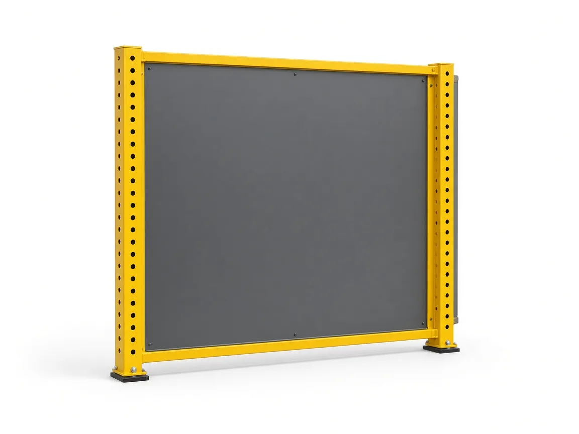
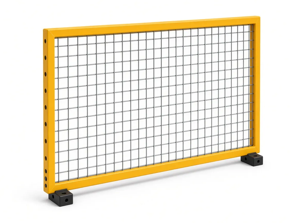
That choice has trade-offs. Wire mesh offers airflow and broad visibility. Polycarbonate can preserve visibility while helping contain chips, coolant, and small parts. Sheet metal is better where flash, spatter, noise, or process contamination are concerns. Use the material that fits the hazard and the process, not just the one that looks simplest on the drawing.
If you need help comparing those options, see Wire Mesh vs Polycarbonate vs Sheet Metal Machine Guards and the product pages for Wire Mesh Panels (D Series) and Polycarbonate Panels (PC Series).
Maintenance and changeover access
Maintenance access should be designed in, not forced later. If technicians need to remove a motor, change a fixture, or clear a jam, the opening must fit the task and the tools. Wide doors, sliding gates, folding gates, or removable service sections may be appropriate, depending on the cell geometry and the access pattern.
Do not create a layout that makes people bypass the guard because the real service route is too tight. If a gate must open for maintenance, the stopping function, lockout method, and restart procedure should be part of the design. Temporary removal of guarding should be controlled and verified before the machine returns to service.
Risk Reduction Decisions Tied to the Assessment
Choose the safeguarding method
Once the hazards and tasks are documented, use the hierarchy of risk reduction in ISO 12100 to choose the safeguarding method. In some areas, a fixed perimeter guard is the best answer because routine access is not required. In others, an interlocked gate is necessary because people must enter the cell for setup, cleaning, or maintenance.
The important point is that each opening needs a documented reason and a corresponding safety function. A good design does not include spare openings “for future use” without a plan. It also does not assume that one device solves every hazard. Guards, gates, control reliability, stopping performance, and safe distances all work together.
For robot applications, start with Robot Cell Guarding or the broader Solutions page if the line includes multiple process types.
Decide gate type and opening size
Select gate style based on the job. Single swing and double swing gates are common for personnel entry. Sliding and folding gates save floor space where a swing path is not practical. Wide gates may be necessary for pallets, carts, or large fixtures. The opening should be large enough for the intended item, but no larger than necessary for safe access.
That decision affects more than the hinge or track. It changes the interlock location, the clear swing area, the possible approach path, and the chance that someone could reach around or through the opening. If forklifts or pallets must pass through, the opening should be treated differently from a normal operator door.
See Safety Gates for common gate types and Palletizing Guarding when the opening must handle pallets or forklifts.
Set safety distances and opening controls
Safety distances should prevent a person from reaching the hazard before motion has stopped. Use the current edition of ISO 13855 and ISO 13857 for the design basis, and verify the actual stopping performance of the machine before finalizing the distance. The exact value depends on the device, stopping time, approach speed, and the opening size or reach possibility in the perimeter.
If your project includes sensing devices, measure and document the stop-time assumptions before you lock the layout. If you want a practical starting point for light curtain calculations, see the Safety Distance Calculator.
Machine Guarding Risk Assessment Checklist
Use this checklist during concept design or RFQ preparation. It is better to answer these questions before the fence is specified than after the line is installed.
| Checklist item | Question to answer | Typical design implication | Evidence or notes to capture |
|---|---|---|---|
| Hazard type | What can cause injury: pinch, crush, shear, entanglement, ejection, thermal, electrical, or stored energy? | Influences guard material, panel strength, and whether impact-resistant or solid panels are needed. | Machine drawings, process description, photos, maintenance notes. |
| Hazard location | Where is the hazard during normal running, setup, cleaning, and maintenance? | Defines the perimeter line and where openings are or are not allowed. | Layout sketch with hazard zones marked. |
| Access frequency | How often do people need to approach or enter the zone? | Frequent access usually pushes the design toward controlled gates or process changes. | Task frequency by shift, week, or month. |
| Task duration | How long does each access event last? | Longer access favors easier, safer access routes and stronger restart control. | Estimated seconds or minutes per task. |
| Who enters | Operator, maintenance, cleaner, integrator, quality, or forklift driver? | Different users may need different gate types or access widths. | Role list and typical path of approach. |
| Visibility need | Must the process be seen during operation? | Drives the choice between mesh, polycarbonate, or solid sheet metal. | Notes on line-of-sight, cameras, or indicators. |
| Largest item through the opening | What is the largest part, tool, pallet, or cart that must pass through? | Sets gate width and height, and may require a special opening style. | Measured dimensions of the largest transfer item. |
| Maintenance access | Does service require entry into the cell or only external access? | Determines gate placement, removable sections, and LOTO approach. | Service procedure, tool list, and access notes. |
| Forklift or pallet traffic | Do materials need to pass through the perimeter? | May require a wide gate, tunnel, or separate transfer opening. | Traffic path, vehicle size, pallet size, turning radius. |
| Approach path | Can someone walk straight to the hazard, or is the access indirect? | Influences opening placement and whether reach-around is possible. | Floor markings, aisle widths, nearby equipment. |
| Stopping performance | What is the actual stop time or stop distance used in the design? | Drives safety distance selection and gate interlock timing. | Measured test data or validated machine data. |
| Change control | Will the process, tooling, or cycle time likely change later? | Encourages a layout that can be revised without unsafe shortcuts. | Planned future changes or expansion notes. |
Practical Examples from the Factory Floor
Robot cell with frequent tool changeover
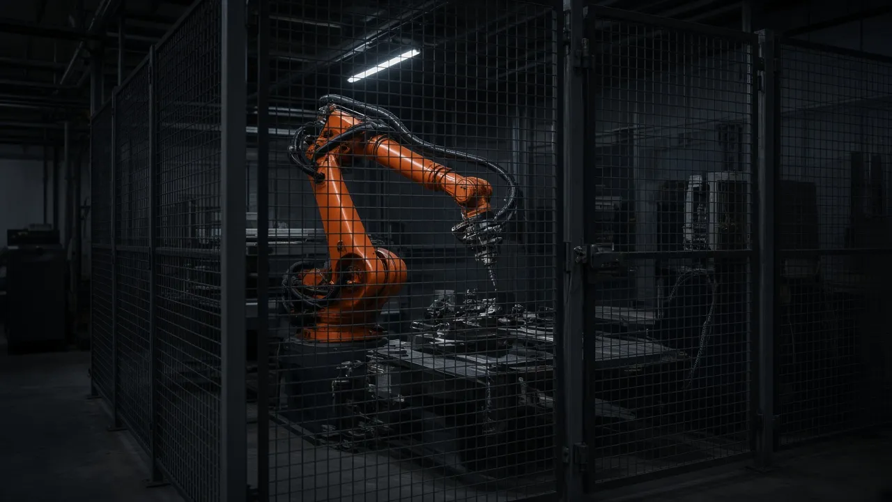
Suppose an integrator is building a robot cell where operators change tooling several times per shift. The hazard is not just the robot motion envelope. It also includes pinch points at the end effector, part handling zones, and the path used to bring in carts or fixtures. In this case, visibility matters because the operator must confirm part position and tool alignment before restarting.
A mixed-material perimeter may be the best fit. Polycarbonate panels can preserve sightlines where needed, while a controlled wide gate handles carts and technician entry. The interlock and stop function must be verified against the actual machine stop time, and the access route should be wide enough that the operator does not feel pushed to prop the gate open during setup.
Conveyor or transfer line with occasional jam clearing
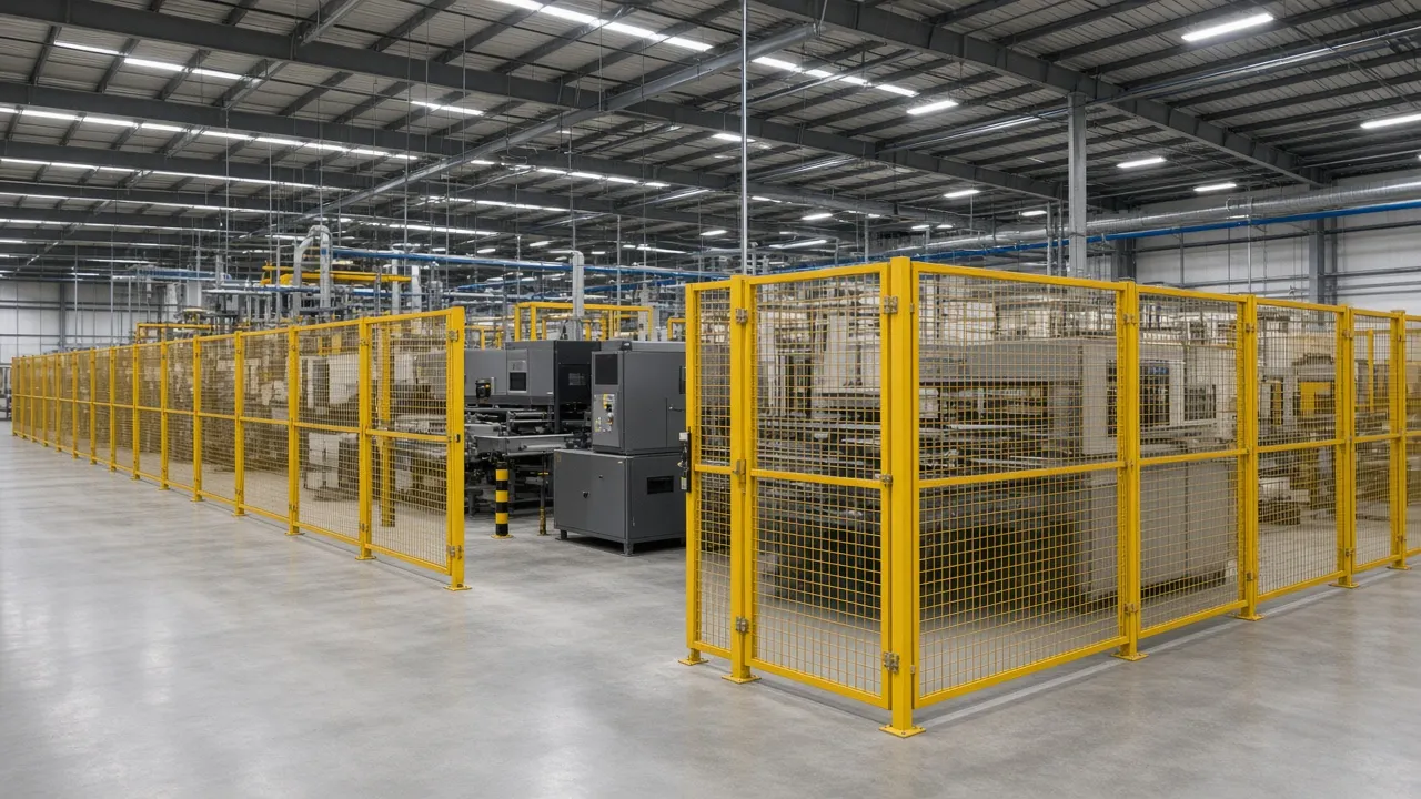
Now consider a conveyor line with transfer points, pinch zones, and occasional product jams. Routine entry is not needed, but maintenance may require access at specific points. Here, a mostly fixed perimeter with one or two controlled service gates often makes more sense than multiple open access points along the line.
Because transfer points are part of the hazard map, the opening locations should be placed where the maintenance task actually occurs, not wherever the layout has leftover space. For this type of line, see Conveyor Guarding and the article Perimeter Guarding for Machines: Design Steps and Examples.
Palletizing or CNC machine tending line
Palletizing and CNC tending lines often need both personnel access and material transfer access. Operators may need to load material, maintenance may need to reach inside for service, and forklifts or pallets may need to cross the perimeter at a separate point. That makes gate planning especially important.
A wide gate is not automatically wrong, but it must be paired with a design that preserves separation between person access and material flow. For CNC tending, chip and coolant containment may also matter, which can point toward polycarbonate in some areas and mesh in others. See CNC Machine Guarding for that application, and review Welding Cell Guarding if flash or spatter is also part of the process.
Common Mistakes That Weaken the Assessment
- Designing the fence before mapping real operator and maintenance tasks.
- Treating every access point the same even though the tasks are different.
- Ignoring jam clearing, cleaning, setup, or troubleshooting when documenting access frequency.
- Assuming visibility is optional when the operator actually needs to observe the process.
- Leaving an opening “for future use” without assigning a current safety function.
- Underestimating the impact of forklifts, pallets, or tool carts on opening size.
- Using one fence height or panel style for every new line without checking the hazard and access profile.
- Failing to update the assessment after a tooling, cycle-time, or layout change.
Move from Assessment to a Guarding Layout
When the assessment is complete, the next step is to turn it into a layout that can be built and quoted. Gather the machine footprint, hazard zones, access points, largest items that must pass through, maintenance needs, and any forklift or pallet movement. That package should become a 2D or 3D guarding layout before you order panels and gates.
If you want a second set of eyes on the concept, Engineering: Send your machine layout, CAD file or basic dimensions. We review access points and safety distances and return a 2D/3D guarding layout before you order. ZYD Technology can also help you choose between mesh, sheet metal, and polycarbonate panels, or between standard and wide gate options, based on the actual process needs.
For a quote, send your layout to Request a quote. If you want a broader overview of how fencing is selected and positioned, review Machine Safety: How safety fencing is selected and positioned. A solid machine guarding risk assessment is the fastest way to avoid layout mistakes, reduce retrofit work, and get a guarding design that fits the line from day one.