OSHA does not have a robot-only guarding rule, so osha machine guarding requirements for robot cells start with 29 CFR 1910.212. In practice, that means protecting employees from point-of-operation hazards, moving parts, and any flying or falling material with physical guarding, controlled access, and a documented risk assessment that fits the actual cell layout.
What OSHA machine guarding requirements mean for robot cells
For robot cells and other automated equipment, OSHA expects hazards to be controlled at the machine, not by warnings alone. The practical question is simple: can a person reach the danger zone while the machine is moving, starting, or releasing energy? If the answer is yes, the guarding concept is incomplete.
In a well-designed cell, the fence, gate, interlock, stop function, and reset logic all work together. The barrier prevents casual access. The interlock stops hazardous motion when access is opened. The reset procedure prevents automatic restart. The geometry of the opening and the distance to the hazard prevent reach-in before motion stops. That is the real-world translation of compliance.
The OSHA rules most relevant to robot and automated equipment guarding
29 CFR 1910.212 — general machine guarding
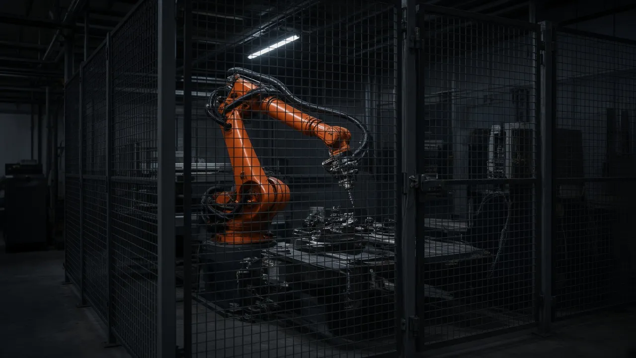
This is the main OSHA machine guarding rule for most industrial machinery. It requires guarding to protect employees from hazards at the point of operation and other exposed moving parts, and from flying chips or sparks where those hazards exist. For robot cells, that usually means a perimeter barrier, protected openings, and controlled access points around the robot, tooling, part transfer areas, and any other hazardous motion inside the cell.
29 CFR 1910.219 — mechanical power-transmission apparatus
If the cell includes conveyors, shafts, belts, chains, couplings, or similar power-transmission components, those hazards also need guarding. In many automated cells, the robot is only one part of the risk picture. The interfaces, transfers, and drives often create pinch points that must be addressed separately.
Equipment-specific rules and consensus standards
If your cell includes specialized equipment, such as presses or press-like systems, additional OSHA requirements may apply. In practice, many engineers use consensus standards to design and validate the guarding concept, including ANSI/A3 R15.06, ISO 12100, ISO 14119, ISO 14120, ISO 13855, and ISO 13857. OSHA remains the enforceable baseline in the U.S.; the current editions of those standards should be checked for the exact application.
For this topic, think of OSHA as the minimum legal framework and the consensus standards as the engineering tools used to build a defensible design.
How engineers translate OSHA expectations into a robot cell layout
Fixed perimeter guarding
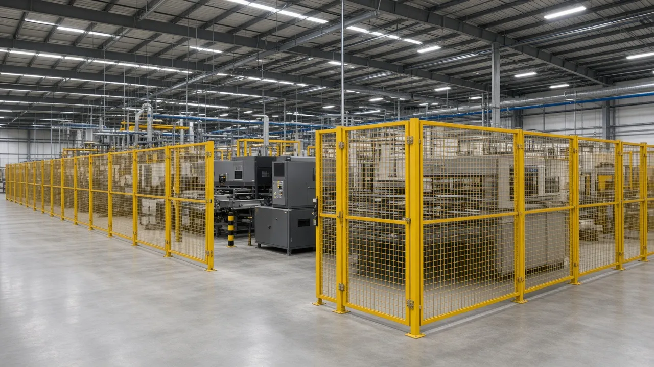
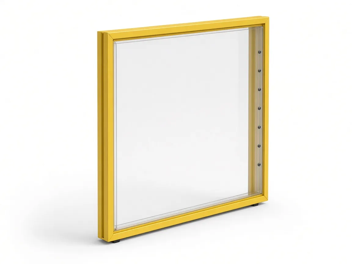
A secure perimeter is the most common starting point for automated cell safety, especially when the robot has a large reach envelope or when the process creates impact, spatter, chips, or other secondary hazards. A modular fence gives you a defined boundary, but the panel type still has to match the process. Wire Mesh Panels (D Series) are a good fit when visibility matters and the hazard is primarily reach-in. Sheet Metal Panels (SM Series) make more sense where welding spatter, dust, or noise is part of the job. Polycarbonate Panels (PC Series) are useful where operators need line of sight but the process also throws chips or coolant.
Access points and why they matter
Every opening in the perimeter is a design decision, not an afterthought. Routine operator access, maintenance access, and material handling access each create different risk profiles. A small load/unload opening may be acceptable in one process, while a pallet transfer opening in another cell may require a wide interlocked gate and a different operating mode. The goal is not just to let people in and out; it is to control when they can enter, how far they can reach, and whether the robot can move while the opening is available.
Safety Gates are the usual answer when access is necessary. For interlocked access, the gate hardware and machine control logic must work as one system. A properly specified Safety Gate Handle Set can support door operation, escape release, LOTO capability, and controlled reset functions for interlocked gates.
Safe distances and opening sizes
Openings and setback distances have to prevent reach-through, reach-around, and reach-over into the hazard zone. That is why engineers commonly use ISO 13857 and ISO 13855 when laying out the perimeter, gate location, and any sensing devices. The exact values depend on the hazard, the opening size, the stop performance, and the application, so the current edition of the applicable standard should always be checked before the final layout is released.
If your design uses light curtains or similar presence-sensing devices, the safety distance must be based on the stop time and approach conditions, not on a guess. A safety distance calculator can help with the arithmetic, but it does not replace a full risk assessment or validation of the final system.
Stop functions and restart control
An interlocked gate should stop hazardous motion in a controlled way, but stopping alone is not enough. The restart sequence matters too. The machine should not resume automatically when the gate closes. A deliberate manual reset outside the hazard zone is the safer approach because it forces the operator to confirm that the area is clear before motion can resume.
A practical decision tree for common robot cell situations
If the operator only loads parts through a small opening
Keep the opening as small as the process allows, and verify that reach-in is prevented in every body position the operator might use. If the part must protrude through the barrier, the depth of the tunnel or pocket should still block access to the hazard. If the geometry is tight, consider adding detection or redesigning the load presentation instead of enlarging the opening.
If forklifts or pallet jacks enter the cell
Use a wide access strategy that separates pedestrian entry from vehicle entry. A pallet gate should not be treated like a normal personnel door. It needs enough clear width for the load, but it also needs controls that keep hazardous robot motion inhibited while the pallet, forklift, or jack is inside the cell.
If maintenance needs frequent entry
Design the access path early. Maintenance teams need room for tools, test fixtures, and sometimes replacement components, but the cell still has to prevent unexpected motion. The gate type, interlock, reset procedure, and LOTO points should all be chosen with service access in mind so technicians do not feel pressured to bypass the safeguard.
If the cell includes welding, machining, or chip/coolant hazards
Choose the guard material around the process, not just around the robot. Sheet metal panels are often the better choice near welding because they help shield nearby workers from arc flash and spatter. Polycarbonate is often better near machining because it helps contain chips and coolant while preserving visibility. Mesh is useful where visibility and airflow matter more than containment.
Table: Guarding choice by hazard and access type
| Scenario | Main hazard | Typical guarding approach | Key design caution | Related standard reference |
|---|---|---|---|---|
| Robot-only cell with infrequent access | Impact, crushing, high-speed arm travel | Fixed perimeter fencing with an interlocked maintenance gate | Verify fence height, opening size, and setback distance before ordering | OSHA 1910.212, ISO 13857 |
| Robotic palletizing cell | Heavy loads, forklift traffic, moving conveyors | Tall perimeter fence with wide interlocked pallet gates | Separate personnel entry from material transfer entry | ISO 12100, ANSI/A3 R15.06 |
| Robotic welding cell | Arc flash, molten spatter, smoke, rapid arm movement | Sheet metal and mesh combination, with interlocked access | Protect against spatter, heat, and degradation of adjacent components | ISO 14120, OSHA 1910.212 |
| CNC machine tending cell | Flying metal chips, coolant spray, robot arm movement | Polycarbonate panels, interlocked operator loading gate | Confirm chemical compatibility and scratch resistance for the environment | ISO 14119, ISO 13857 |
| Conveyor transfer opening | Nip points, in-running rollers, product jams | Tunnel guards or restricted pass-through slots with sensing | Avoid creating a new pinch point at the transfer boundary | OSHA 1910.212, where applicable 1910.219 |
| Maintenance access door | Unexpected restart, trapped personnel | Interlocked swing or sliding gate with manual reset and LOTO | Verify the stop performance and safety distance are sufficient to prevent reach-in before motion ceases | ISO 14119, ISO 13849-1 |
Common mistakes that create OSHA problems
- Oversized access openings: Cutting large holes in fences for convenience without checking whether a hand, arm, or tool can still reach the hazard.
- Improper restart logic: Letting the machine resume immediately when the gate closes instead of requiring a deliberate reset.
- Relying on administrative controls: Using signs, floor tape, or verbal instruction where physical guarding is still needed.
- Overlooking peripheral hazards: Guarding the robot arm while leaving conveyors, drives, or transfer points exposed.
- Gaps at the floor line: Leaving enough clearance under panels for feet, tools, or materials to slip underneath.
- Bypass-friendly routing: Running cables, air hoses, or fixtures through the fence in a way that creates a climb point or an easy bypass.
What to document before the guard design is finalized
A good machine guarding package is built on paper first. Before anyone starts cutting posts or ordering panels, the team should document the hazards, access needs, and safety functions that drive the design.
Checklist for the design file
- Identify every access point and classify it as operator, maintenance, or material handling access.
- List every hazard inside and outside the cell, including robot motion, conveyors, drives, tooling, drops, spatter, chips, and coolant.
- Confirm who needs entry, how often they need to enter, and what tools or material they carry.
- Define the gate type, interlock logic, stop function, and manual reset method.
- Verify reach distances, opening sizes, and safety setbacks against the current applicable standards.
- Document lockout/tagout steps and any bypass or recovery procedure that service personnel may need.
- Validate the completed system before production starts.
A documented risk assessment by a qualified person should be part of that file. If the cell changes later, the assessment and the guarding layout should be updated too.
Example layouts
Example 1 — robotic palletizing cell
A palletizing cell often needs a tall perimeter fence around the robot, conveyor interface, and pallet buildup area. The wide pallet opening should be controlled by a gate or other safeguarding method that prevents access to the hazard while pallets move in and out. A separate personnel gate is usually better than using the pallet opening for everything.
Example 2 — robotic welding cell
A welding cell usually benefits from sheet metal panels around the active weld zone and mesh in places where the operator needs visibility. Interlocked maintenance access should be located so the robot cannot continue welding or sweeping motion when the gate is opened. If a positioner is part of the cell, treat that equipment as a separate hazard source and guard it accordingly. For application-specific layouts, see Welding Cell Guarding.
Example 3 — CNC machine tending cell
When a robot loads and unloads a CNC machine tool, the guard has to address chips, coolant, doors, and the robot arm. Polycarbonate panels are often used where line of sight matters and the process throws material toward the perimeter. The operator gate should allow safe access for part loading or cleaning, but only when the machine and robot are in a safe state. For more on this application, review CNC Machine Guarding.
How to spec a robot-cell fence without overcomplicating it
Start with the hazard and the task, not with the panel catalog. Define who needs access, what they need to do, how often they need to do it, and how the cell will behave when access is opened. Then choose the fence material, gate type, and control logic that match the actual work. If the process is still moving fast and the design is not clear, slow down and validate the layout before buying hardware.
For a broader framework, see Robot Cell Guarding and Machine Safety. If you are building a new cell or revising an older one, a layout review before purchase often catches access, distance, and gate issues that are expensive to fix after installation.
Conclusion
Meeting osha machine guarding requirements in a robot cell is less about picking a fence and more about designing a complete safeguarding system. The best results come from matching the barrier, gate, distance, and control logic to the task, then documenting the risk assessment and validating the finished layout. If you want a practical starting point, send your layout, CAD file, or basic dimensions to Engineering for a guarding review, or use Request a quote to begin the proposal process.