When buying or integrating an automated workcell, verifying ANSI R15.06 robot safety is essential to protecting people and avoiding expensive redesigns. In practice, ANSI/A3 R15.06 is the framework U.S. buyers should use to review the whole robot cell, together with ISO 10218 and a documented risk assessment that covers guarding, access, safety distances, and integration responsibilities.
What ANSI/A3 R15.06 Means for a Robot Cell Purchase
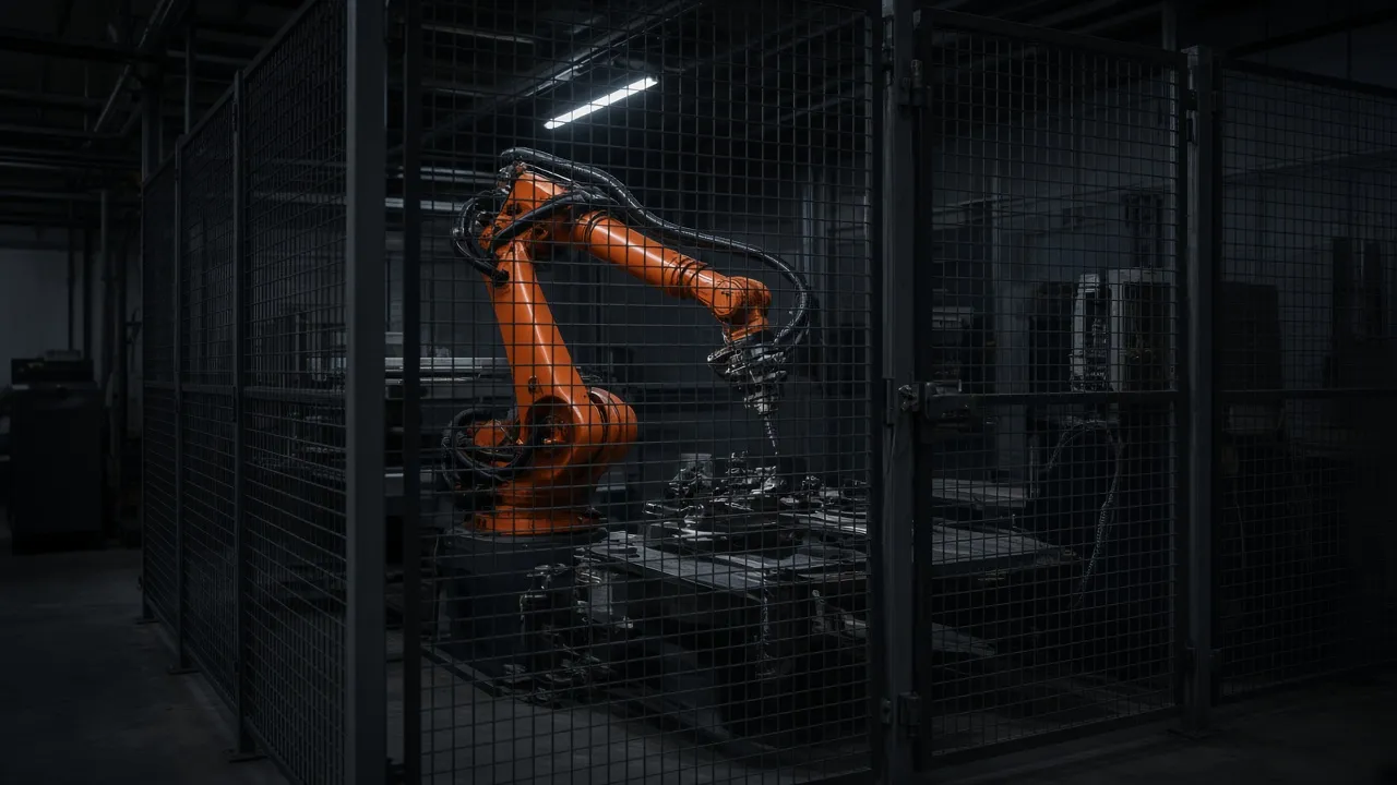
Many buyers focus on the robot arm and assume the rest of the cell will be handled automatically. That is not enough. The standard framework applies to the complete robot system: the manipulator, controller, end effector, tooling, part transfer, perimeter guarding, and the way people enter or interact with the cell.
For a U.S. buyer, the practical question is simple: does the proposed design actually control the hazards created by the specific application? A compliant robot component does not, by itself, make a safe robot cell. The full system must be assessed as a whole.
If you are scoping a new cell, start with the application, not the hardware. A robot palletizing line, welding cell, and machine-tending system each create different hazards and access needs. That is why the guarding package should be reviewed as part of the layout, not added after the robot is selected. For application-specific examples, see Robot Cell Guarding and machine guarding solutions for robot cells and automated equipment.
Why the Standard Matters to Buyers, Not Just Integrators
It Affects the Layout, Not Just the Electrical Design
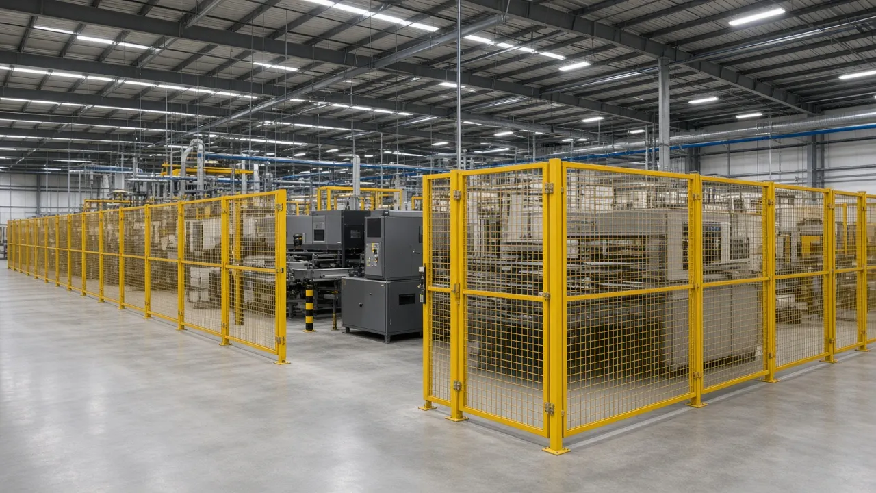
Safety controls are only one part of the equation. Fence location, gate placement, opening size, and access routes all affect the residual risk. If an operator can reach a hazard through a transfer opening, or step into a hazardous zone before motion has stopped, the cell is not correctly laid out—even if the safety PLC is programmed correctly.
The physical layout must be driven by the actual hazard points: robot reach, tooling swing, fixture motion, conveyors, pallets, and any auxiliary equipment tied into the cell. That is why perimeter design should be part of the early engineering review, not a late-stage add-on.
It Affects Procurement Language
A phrase like “design to ANSI/A3 R15.06” is not enough by itself. Buyers should ask for the scope, the assumptions, the risk assessment owner, the validation owner, and the documents that will be delivered at turnover. That keeps the RFQ specific enough to compare proposals and avoid gaps later.
How ANSI/A3 R15.06 Relates to ISO 10218 and Risk Assessment
ANSI/A3 R15.06 is the U.S. framework commonly used for industrial robot and robot system safety. It is aligned with ISO 10218-1 and ISO 10218-2, which address the robot and the robot system/integration side of the application. In practice, the buyer should verify that the design basis is current, that the current edition is being applied, and that the project includes a documented risk assessment by a qualified person.
That risk assessment should identify hazards, estimate the risks, define risk reduction measures, and confirm that the final layout and controls actually address the real machine and workflow. It should cover normal production, teaching, cleaning, maintenance, fault recovery, and any temporary access conditions. Applicable OSHA requirements and plant procedures still matter as well; the standards do not replace them.
Buyer Checklist: What to Verify Before You Buy
Use this checklist during design review, RFQ evaluation, or pre-order approval. If any item is unclear, ask for the supporting drawing or calculation before you release the purchase order.
| Item to Verify | Why It Matters | What Evidence to Request | Typical Red Flag |
|---|---|---|---|
| Perimeter layout | Controls access to all robot and auxiliary hazards. | Dimensioned 2D/3D layout showing the full boundary and all hazard points. | Fence drawn from a generic template instead of the actual cell geometry. |
| Access gates | Gates determine how people enter for operation, service, and maintenance. | Gate schedule, hardware type, interlock method, and opening direction. | A service gate added late without a safety review. |
| Protected openings | Material flow openings can become reach-in points if they are not controlled. | Details for tunnels, muting, light curtains, or mechanical barriers where used. | A pallet or part opening that can be used as a hand access point. |
| Safety distances | People must not reach the hazard before the machine stops or is otherwise protected. | Measured stopping time and the calculation method used for the actual device and layout. | Distance based on assumption instead of test data. |
| Stop and restart logic | The cell should not resume unexpectedly after a gate closes or a fault clears. | Control narrative, safety function list, and reset/restart sequence. | Unclear restart behavior after gate closure or E-stop reset. |
| Maintenance access | Technicians need a safe way to clear faults, clean, and service equipment. | LOTO procedure, teach mode details, and any reduced-speed or hold-to-run methods. | No documented safe method for internal access. |
| Validation package | The design must be checked after installation and before production use. | Functional safety validation, test records, and commissioning sign-off. | Project handoff with drawings only and no validation evidence. |
Common Robot Cell Layout Decisions That Create Compliance Problems
Too Much Access, Not Enough Distance
A common mistake is placing a fence too close to the hazard and assuming the robot will stop in time. Another is leaving a large opening for parts, pallets, or tooling and treating it as a minor detail. If an operator can reach through an opening or walk through a gate before the hazard is controlled, the layout must be revised.
This is where a measured stopping time and the correct distance calculation matter. The exact method depends on the device, the application, and the current standard edition. If the cell includes presence-sensing devices or safety light curtains, use the project’s actual data instead of a generic estimate. A related tool that can help with speed-and-distance thinking is the Safety Distance Calculator, which explains the basic approach used for light curtain applications.
Choosing the Wrong Guarding Material
Material selection should support the hazard, the process, and the visibility needs of the cell. It does not, by itself, determine compliance, but it can make a good layout easier to use and maintain:
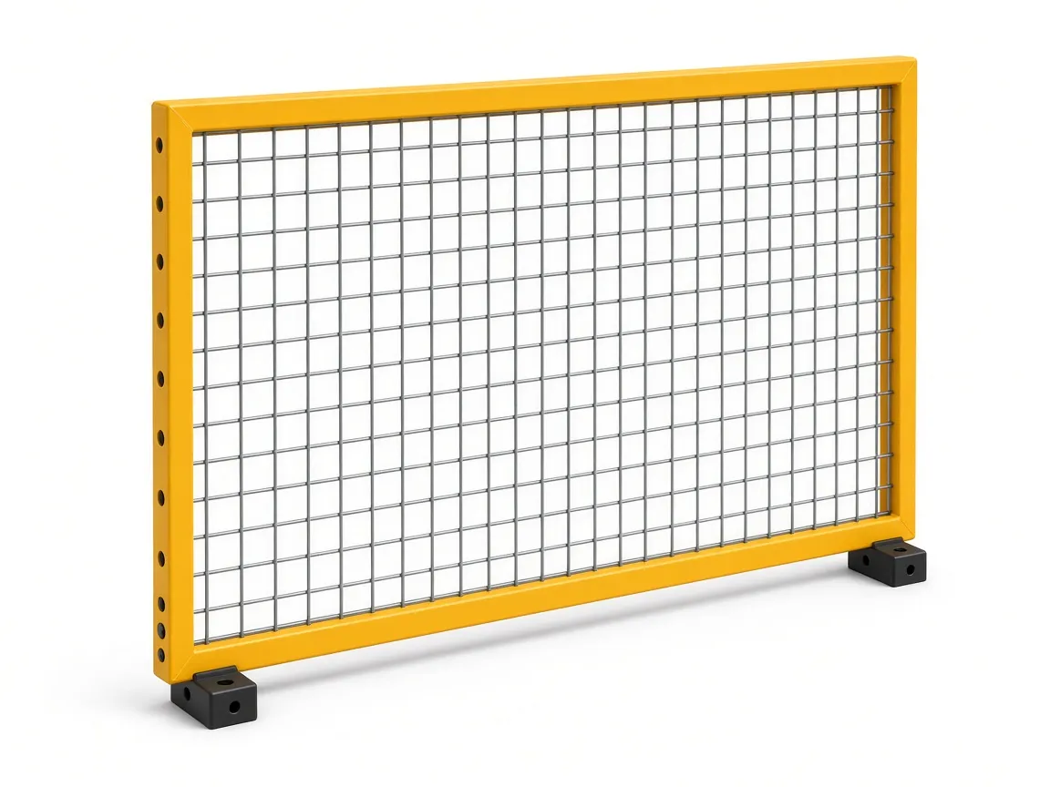
- Wire mesh is a practical choice for general robot perimeters where operators need visibility and ventilation. See Wire Mesh Panels (D Series).
- Sheet metal is often better where the process produces flash, spatter, chips, or noise, such as in welding cells. See Sheet Metal Panels (SM Series).
- Polycarbonate is useful where visibility is important and the process needs containment of chips, coolant, or small parts. See Polycarbonate Panels (PC Series).
For a deeper comparison of the trade-offs, see Wire Mesh vs Polycarbonate vs Sheet Metal Machine Guards.
Gate Design Mistakes
Gate design should match how the cell is actually used. A single swing gate may work for a narrow service entrance, while a sliding or double gate may be better for larger access needs or traffic paths. The right answer depends on whether the user needs routine entry, maintenance access, part changeover, or a wide opening for tooling or pallets.
As a rule, the gate hardware and interlock arrangement should be selected from the risk assessment, not from convenience. A proper gate package may include interlocked access, escape release where needed, and a reset arrangement that supports safe operation. See Safety Gates and Safety Gate Handle Set for common hardware options used in modular guarding systems.
Practical Example: A Robotic Palletizing Cell
Consider a palletizing cell feeding finished cartons to outbound pallets. The cell needs room for pallet infeed, fork access, and operator intervention at the end of the line. The perimeter must protect the robot and the pallet transfer area without turning normal logistics into a bypass problem.
In this case, the buyer should verify that the fence layout includes wide but controlled access points for pallet movement, and that the service gate is not the only thing separating people from the hazard. A protected transfer opening may be needed, but it should be designed so a person cannot use it as a shortcut into the cell. If forklift traffic comes close to the boundary, the posts, panels, and gate hardware should be positioned to reduce strike risk and keep the walking access path outside the hazardous zone. For a related application view, see Palletizing Guarding.
Practical Example: A Robotic Welding Cell
A robotic welding cell creates a different set of problems. The hazard is not only the robot motion, but also flash, spatter, heat, and positioner motion. Visibility matters, but so does containment. If the operator must inspect parts or load fixtures, the access point must be designed so the person cannot enter while the robot or positioner can move unexpectedly.
That often leads to a combination of sheet metal near the process and mesh where visibility and ventilation matter. The access method for torch service, fixture change, or part loading should be resolved during the layout phase, not after the cell is built. For more on this application, see Welding Cell Guarding.
What a Complete Layout Package Should Include
Before you approve the cell, ask for a layout package that shows how the guarding will be built, installed, and validated. A useful package should include:
- A dimensioned 2D floor plan with all hazard points, fence lines, gates, and transfer openings.
- A 3D concept or model showing access paths, gate swings or slides, and equipment interfaces.
- A panel and gate schedule listing the guarding type used at each side of the cell.
- The safety function list and the validation plan for the final installed system.
- A responsibility matrix showing who owns the risk assessment, installation, testing, and turnover documents.
If you are still at the concept stage, send your machine layout, CAD file, or basic dimensions to Engineering. A layout review before ordering can catch access and distance problems before they become field changes.
RFQ Questions U.S. Buyers Should Ask Every Integrator
These questions help separate a complete proposal from a vague one:
- Which current edition of ANSI/A3 R15.06 and which ISO 10218 basis are you using for this design?
- Who is performing the risk assessment, and will the result be part of the turnover package?
- What measured stopping times were used to set the fence and gate distances?
- How are access gates controlled during operation, maintenance, and fault recovery?
- What prevents restart after a gate is closed or a fault is cleared?
- Which openings are for material flow only, and how are they protected from human access?
- What validation tests will be performed before the cell is released for production?
If the answers are vague, the design is probably not ready for purchase. If the answers are specific and documented, the project is much easier to build, validate, and support.
For buyers who want a second set of eyes on the layout, ZYD Technology can review your machine layout, CAD file, or basic dimensions and return a guarding proposal before you order. Contact the team or use Request a quote to start the review.
Bottom line: ANSI R15.06 robot safety is not just about the robot itself. The standard framework, together with ISO 10218 and a documented risk assessment, should drive the perimeter, access points, safety distances, and validation plan for the actual cell you are buying.